Giỏ hàng đang trống!
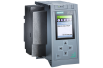
Micromaster MM430
MICROMASTER MM430


Overview
Application
The MICROMASTER 430 inverter is suitable for a variety of variable-speed drive applications. Its flexibility provides for a wide spectrum of applications. It is especially suitable for use with industrial pumps and fans.
The inverter is especially characterized by its customer-oriented performance and ease-of-use. It has more inputs and outputs than the MICROMASTER 420, an optimized operator panel with manual/automatic switchover, and adapted software functionality.
Design
The MICROMASTER 430 inverter has a modular design. The operator panels and communication modules can be easily exchanged.
Main characteristics
-
Easy, guided start-up
-
Modular construction allows maximum configuration flexibility
-
Six programmable isolated digital inputs
-
Two scaleable analog inputs (0 V to 10 V, 0 mA to 20 mA) can also be used as a 7th/8th digital input
-
Two programmable analog outputs (0 mA to 20 mA)
-
Three programmable relay outputs
30 V DC/5 A, resistive load
250 V AC/2 A, inductive load -
Low-noise motor operation thanks to high pulse frequencies, adjustable (observe derating if necessary)
-
Protection for motor and inverter
-
Control of up to three additional drives on the basis of PID control (motor staging)
-
Operation of drive directly on mains (with external bypass circuit)
-
Low-energy mode
-
Detects dry run of pumps (belt failure detection)
Options (overview)
-
Line commutating chokes
-
Output chokes
-
LC filter and sinusoidal filter
-
Gland plates
-
Basic Operator Panel 2 (BOP-2) for parameterizing the inverter
-
Communication modules
-
PROFIBUS
-
DeviceNet
-
CANopen
-
-
PC connection kits
-
Mounting kits for installing the operator panels in the control cabinet doors
-
PC start-up tools, executable under Windows 98/NT/2000/ME/XP Professional
-
TIA integration with Drive ES
International standards
-
The MICROMASTER 430 inverter complies with the requirements of the EU low-voltage guideline.
-
The MICROMASTER 430 inverter has CE marking.
-
Acc. to UL and c UL certified
-
c-tick
Mechanical features
-
Modular design
-
Operating temperature: –10 °C to +40 °C (+14 °F to +104 °F)
-
Compact housing as a result of high power density
-
Easy cable connection, mains and motor connections are separated for optimum electromagnetic compatibility
-
Detachable operator panels
-
Screwless control terminals on detachable I/O board
Performance features
-
Latest IGBT technology
-
Digital microprocessor control
-
Flux Current Control (FCC) for improved dynamic response and optimized motor control
-
Linear V/f characteristic
-
Quadratic V/f characteristic
-
Multipoint characteristic (programmable V/f characteristic)
-
Flying restart
-
Slip compensation
-
Automatic restart facility following power failure or fault
-
Energy saving mode (stopping e.g. of a pump at low speeds)
-
Motor staging (connection and disconnection of additional motors, use of inverter as control drive in a pump cascade)
-
Manual/automatic mode
-
Load torque monitoring (belt failure detection; detects dry run of pumps)
-
High-grade internal PID controller for simple process control
-
Programmable acceleration/deceleration times, 0 s to 650 s
-
Ramp smoothing
-
Fast Current Limit (FCL) for trip-free operation
-
Fast, repeatable digital input response time
-
Fine adjustment using two high-resolution 10-bit analog inputs
-
Compound braking for rapid controlled braking
-
Four skip frequencies
-
Removable “Y” capacitor for use on IT systems (with non-grounded mains supplies, the “Y” capacitor must be removed, and an output choke installed)
Protection features
-
Overload capability
-
7.5 kW to 90 kW:
Overload current 1.4 x rated output current (i.e. 140 % overload capability) for 3 s and 1.1 x rated output current (i.e. 110 % overload capability) for 60 s, cycle time 300 s -
110 kW to 250 kW:
Overload current 1.5 x rated output current (i.e. 150 % overload capability) for 1 s and 1.1 x rated output current (i.e. 110 % overload capability) for 59 s, cycle time 300 s
-
-
Overvoltage/undervoltage protection
-
Inverter overtemperature protection
-
Special direct connection for PTC or KTY to protect the motor
-
Earth fault protection
-
Short-circuit protection
-
I2t motor thermal protection
-
Locked motor protection
-
Stall prevention
-
Parameter interlock
Technical specifications
| Technical data | MICROMASTER 430 | |||
|---|---|---|---|---|
| Mains voltage and power ranges | 380 V to 480 V 3 AC ±10 % | 7.5 kW to 250 kW (variable torque) | ||
| Power frequency | 47 Hz to 63 Hz | |||
| Output frequency | for inverter 7.5 kW to 90 kW | 0 ... 650 Hz, (limitation to 550 Hz in production to comply with legal requirements) 1) | ||
| for inverter 110 kW to 250 kW | 0 Hz to 267 Hz | |||
| Power factor | ≥ 0.95 | |||
| Inverter efficiency |
for inverter 7.5 kW to 90 kW | 96 % to 97 % | ||
| for inverter 110 kW to 250 kW | 97 % to 98 % | |||
| (Further information is available on the Internet at: http://support.automation.siemens.com/WW/view/en/22978972) |
||||
| Overload capability |
for inverter 7.5 kW to 90 kW | Overload current 1.4 x rated output current (i.e. 140 % overload capability) for 3 s and 1.1 x rated output current (i.e. 110 % overload capability) for 60 s, cycle time 300 s | ||
| for inverter 110 kW to 250 kW | Overload current 1.5 x rated output current (i.e. 150 % overload capability) for 1 s and 1.1 x rated output current (i.e. 110 % overload capability) for 60 s, cycle time 300 s | |||
| Inrush current | less than rated input current | |||
| Control method | linear V/f characteristic; quadratic V/f characteristic; multipoint characteristic (programmable V/f characteristic); flux current control (FCC); energy saving mode | |||
| Pulse frequency | for inverter 7.5 kW to 90 kW | 4 kHz (standard) 2 kHz to 16 kHz (in 2-kHz-steps) |
||
| for inverter 110 kW to 250 kW | 2 kHz (standard) 2 kHz to 4 kHz (in 2-kHz-steps) |
|||
| Fixed frequencies | 15, programmable | |||
| Skip frequency ranges | 4, programmable | |||
| Setpoint resolution | 0.01 Hz digital 0.01 Hz serial 10 bit analog |
|||
| Digital inputs | 6 fully programmable isolated digital inputs; switchable PNP/NPN | |||
| Analog inputs |
2 programmable analog inputs
|
|||
| Relay outputs | 3, programmable 30 V DC/5 A (resistive load), 250 V AC/2 A (inductive load) |
|||
| Analog outputs | 2, programmable (0/4 mA to 20 mA) | |||
| Serial interfaces | RS-485, option RS-232 | |||
| Motor cable length | for inverter 7.5 kW to 90 kW | Without output choke | max. 50 m (shielded) max. 100 m (unshielded) |
|
| With output choke | See variant dependent options | |||
| for inverter 110 kW to 250 kW | Without output choke | max. 200 m (shielded) max. 300 m (unshielded) |
||
| With output choke | See variant dependent options | |||
| Electromagnetic compatibility |
for inverter 7.5 kW to 90 kW | Inverter with internal filter Class A available | ||
| for inverter without filter | 7.5 kW to 15 kW | EMC filter Class B to EN 55 011 available as an option | ||
| 18.5 kW to 90 kW | EMC filter Class B from Schaffner available as an option | |||
| 110 kW to 250 kW | EMC filter Class A available as an option | |||
| Braking | DC braking, compound braking | |||
| Degree of protection | IP20 | |||
| Operating temperature range |
for inverter 7.5 kW to 90 kW | -10 °C to +40 °C (+14 °F to +104 °F) | ||
| for inverter 110 kW to 250 kW | 0 °C to +40 °C (+32 °F to +104 °F) | |||
| Storage temperature | -40 °C to +70 °C (-40 °F to +158 °F) | |||
| Relative humidity | 95 % (non-condensing) | |||
| Installation altitude |
for inverter 7.5 kW to 90 kW | up to 1000 m above sea level without derating | ||
| for inverter 110 kW to 250 kW | up to 2000 m above sea level without derating | |||
| Standard SCCR (Short Circuit Current Rating) 2) |
FSC: 100 kA FSD, FSE, FSF, FSFX, FSGX: 65 kA |
|||
| Protection features for | undervoltage, overvoltage, overload, earth faults, short-circuits, stall prevention, locked motor protection, motor overtemperature, inverter overtemperature, parameter change protection | |||
| Conformity with standards | for inverter 7.5 kW to 90 kW | UL, cUL, CE, c-tick | ||
| for inverter 110 kW to 250 kW | UL available soon, cUL available soon, CE | |||
| CE marking | Conformity with low-voltage directive 73/23/EEC | |||
| Cooling-air volumetric flow required, dimensions and weights (without options) |
Frame size (FS) | Cooling-air volumetric flow required (l/s)/(CFM) | H x W x D (mm) | Weight, approx. (kg) |
| C | 54.9/116.3 | 245 x 185 x 195 | 5.7 | |
| D | 2 x 54.9/2 x 116.3 | 520 x 275 x 245 | 17 | |
| E | 2 x 54.9/2 x 116.3 | 650 x 275 x 245 | 22 | |
| F without filter | 150/317.79 | 850 x 350 x 320 | 56 | |
| F with filter | 150/317.79 | 1150 x 350 x 320 | 75 | |
| FX | 225/478.13 | 1400 x 326 x 356 | 116 | |
| GX | 440/935 | 1533 x 326 x 545 | 174 | |
| CFM: Cubic Feet per Minute |
|
|
||
1) For further information see http://support.automation.siemens.com/WW/view/en/107669667
2) Applies to industrial control cabinet installations to NEC article 409/UL 508A.
Derating data
Pulse frequency
|
Output
(for 400 V 3 AC) |
Rated output current in A
for a pulse frequency of |
|||||||
|---|---|---|---|---|---|---|---|---|
|
kW
|
2 kHz
|
4 kHz
|
6 kHz
|
8 kHz
|
10 kHz
|
12 kHz
|
14 kHz
|
16 kHz
|
|
7.5
|
19.0
|
19.0
|
17.1
|
15.2
|
13.3
|
11.4
|
9.5
|
7.6
|
|
11.0
|
26.0
|
26.0
|
24.7
|
23.4
|
20.8
|
18.2
|
15.6
|
13.0
|
|
15.0
|
32.0
|
32.0
|
28.8
|
25.6
|
22.4
|
19.2
|
16.0
|
12.8
|
|
18.5
|
38.0
|
38.0
|
36.1
|
34.2
|
30.4
|
26.6
|
22.8
|
19.0
|
|
22
|
45.0
|
45.0
|
40.5
|
36.0
|
31.5
|
27.0
|
22.5
|
18.0
|
|
30
|
62.0
|
62.0
|
55.8
|
49.6
|
43.4
|
37.2
|
31.0
|
24.8
|
|
37
|
75.0
|
75.0
|
71.3
|
67.5
|
60.0
|
52.5
|
45.0
|
37.5
|
|
45
|
90.0
|
90.0
|
81.0
|
72.0
|
63.0
|
54.0
|
45.0
|
36.0
|
|
55
|
110.0
|
110.0
|
93.5
|
77.0
|
63.3
|
49.5
|
41.3
|
33.0
|
|
75
|
145.0
|
145.0
|
123.3
|
101.5
|
83.4
|
65.3
|
54.4
|
43.5
|
|
90
|
178.0
|
178.0
|
138.0
|
97.9
|
84.6
|
71.2
|
62.3
|
53.4
|
|
110
|
205.0
|
180.4
|
-
|
-
|
-
|
-
|
-
|
-
|
|
132
|
250.0
|
220.0
|
-
|
-
|
-
|
-
|
-
|
-
|
|
160
|
302.0
|
265.8
|
-
|
-
|
-
|
-
|
-
|
-
|
|
200
|
370.0
|
325.6
|
-
|
-
|
-
|
-
|
-
|
-
|
|
250
|
477.0
|
419.8
|
-
|
-
|
-
|
-
|
-
|
-
|
Compliance with standards
CE marking
The MICROMASTER inverters meet the requirements of the Low-Voltage Directive 73/23/EEC.
Low-voltage directive
The inverters comply with the following standards listed in the Official Journal of the European Communities:
-
EN 60 204
Safety of machinery, electrical equipment of machines
-
EN 61 800-5-1
Electrical power drive systems with variable speed - Part 5-1: Requirements regarding safety - electrical, thermal and energy requirements
Machine directive
The inverters are suitable for installation in machines. Compliance with the machine directive 89/392/EEC requires a separate certificate of conformity. This must be furnished by the plant constructor or the installer of the machine.
EMC directive
Machine directive
The inverters are suitable for installation in machines. Compliance with the machine directive 89/392/EEC requires a separate certificate of conformity. This must be furnished by the plant constructor or the installer of the machine.
EMC directive
-
EN 61 800-3
Variable-speed electric drives
Part 3: EMC product standard including special test procedure.
The new EMC product standard EN 61 800-3 applies to electrical drive systems as of July 1, 2005. The transition period for the preceding standard EN 61 800-3/A11 dated February 2001 ends on October 1, 2007. The following explanations apply to frequency inverters of the 6SE6 series from Siemens:
-
The EMC product standard EN 61 800-3 does not apply directly to a frequency inverter but to a PDS (Power Drive System), which comprises the complete circuitry, motor and cables in addition to the inverter.
-
As a rule, frequency inverters are only supplied to qualified technical specialists for installation in machines or plants. A frequency inverter must therefore only be considered as a component which, as such, is not subject to the EMC product standard EN 61 800-3. However, the inverter's instruction manual specifies the conditions under which the product standard can be complied with if the frequency inverter is expanded to become a PDS. For a PDS, the EMC directive in the EU is complied with through observance of the product standard EN 61 800-3 for variable-speed electrical drive systems. The frequency inverters on their own do not generally require marking according to the EMC directive.
-
The new EN 61 800-3 of July 2005 no longer distinguishes between "general availability" and "restricted availability". Instead, different categories, namely C1 to C4, are defined according to the environment of the PDS at the place of use:
-
Category C1:
Drive systems for rated voltages of < 1000 V for use in the first environment -
Category C2:
Fixed-location drive systems which are not connected by means of plug-in devices, for rated voltages of < 1000 V. if used in the first environment, installation and start-up may only be carried out by qualified EMC personnel. Warning information must be provided. -
Category C3:
Drive systems for rated voltages of < 1000 V, solely for use in the second environment. Warning information must be provided. -
Category C4:
Drive systems for rated voltages of ≥ 1000 V or for rated currents of ≥ 400 A or for use in complex systems in the second environment. An EMC plan must be drawn up.
-
-
In the EMC product standard EN 61 800-3, limits for conducted interference voltages and radiated interference are also indicated for the so-called "second environment" (= industrial power supply systems which do not supply households). These limits are lower than the limits of filter class A according to EN 55 011. The use of unfiltered inverters in an industrial environment is permissible provided they are part of a system that is equipped with line filters on the higher-level infeed side.
-
With MICROMASTER, power drive systems (PDS) which comply with EMC product standard EN 61 800-3 can be installed (see the installation instructions in the product documentation). The table entitled "Overview of MICROMASTER components and PDS categories" and the MICROMASTER ordering documents show which components the respective PDS installation supports directly.
-
In general, a distinction must be made between the product standards for electrical drive systems (PDS) of the EN 61 800 series of standards (of which Part 3 covers EMC topics) and the product standards for devices/systems/machines etc. This will probably not result in any changes in the practical use of frequency inverters. Since frequency inverters are always part of a PDS and the latter is part of a machine, the manufacturer of the machine must observe various standards depending on the type of machine and the environment, e.g. EN 61 000-3-2 for power supply harmonics and EN 55 011 for radio interference. The PDS product standard alone is therefore inadequate or irrelevant.
-
With regard to compliance with limits for power supply harmonics, the EMC product standard EN 61 800-3 for PDS refers to compliance with the EN 61 000-3-2 and EN 61 000-3-12 standards.
-
Irrespective of configuration with MICROMASTER and its components, the machine builder can also modify the machines in other ways in order to comply with the EMC directive of the EU. As a rule, the EMC directive of the EU is observed through compliance with the EMC product standards applicable to the machine. If they are not available, the generic standards such as DIN EN 61 000-x-x can be used instead. What is important is that the conducted interference and the radiated interference voltages at the power-supply connection point and outside the machine remain below the corresponding limits. What technical means are used to ensure this is not prescribed.
Overview of MICROMASTER components and PDS categories
|
|
|
|---|---|
|
First environment
(residential, commercial) |
Category C1
Unfiltered devices plus external Class B filter with low leakage currents |
|
Category C2
Devices with an integrated Class B filter or devices with an integrated Class A filter plus external supplementary filter Class B or devices with an integrated Class A filter plus warning information or unfiltered devices plus external Class A filter plus warning information |
|
|
Second environment
(industrial) |
Category C2
Devices with an integrated Class B filter or devices with an integrated Class A filter plus external supplementary filter Class B or devices with an integrated Class A filter or unfiltered devices plus external Class A filter Note: The requirements of EN 61 800-3 are considerably exceeded if Class B filters are used. |
|
Category C3
Devices with integrated Class A filter or unfiltered devices plus external Class A filter Warning information is necessary. Note: The requirements of EN 61 800-3 are considerably exceeded if Class A filters are used. |
|
|
Category C4
Unfiltered devices plus external Class A filter An EMC plan must be drawn up. Note: The requirements of EN 61 800-3 are considerably exceeded if Class A filters are used. |
Electromagnetic compatibility
No inadmissible electromagnetic emissions occur if the installation instructions specific to the product are correctly observed.
The table below lists the results of measurements relating to the emissions and immunity to interference of MICROMASTER inverters.
The inverters were installed with shielded motor cables and shielded control cables in accordance with the directives.
|
EMC phenomenon
Standard/test |
Relevant criteria
|
Limit value
|
|
|---|---|---|---|
|
Emitted interference
EN 61 800-3 |
Conducted via mains cable
|
150 kHz to 30 MHz
|
Unfiltered devices, not tested.
All devices with an internal/external filter: Depending on the type of filter and on the envisaged PDS installation: Category C1: Limit value complies with EN 55 011, Class B Category C2: Limit value complies with EN 55 011, Class A, Group 1. In addition, all devices with an internal/external filter comply with the limit value for category C3 installations. Limit value complies with EN 55 011, Class A, Group 2. |
|
Emitted by the drive
|
30 MHz to 1 GHz
|
All devices.
Limit value complies with EN 55 011, Class A, Group 1. |
|
|
ESD immunity
EN 61 000-4-2 |
ESD through air discharge
|
Test severity level 3
|
8 kV
|
|
ESD through contact discharge
|
Test severity level 3
|
6 kV
|
|
|
Immunity to electrical fields
EN 61 000-4-3 |
Electrical field applied to unit
|
Test severity level 3
80 MHz to 1 GHz |
10 V/m
|
|
Immunity to burst interference
EN 61 000-4-4 |
Applied to all cable terminations
|
Test severity level 4
|
4 kV
|
|
Surge immunity
EN 61 000-4-5 |
Applied to mains cables
|
Test severity level 3
|
2 kV
|
|
Immunity to RFI emissions, conducted
EN 61 000-4-6 |
Applied to mains, motor and control cables
|
||
Không có sản phẩm trong danh mục này.


Kinh doanh và Hỗ trợ kỹ thuật
- Hotline/Zalo: 0982.121.771
- Liên hệ: info@sistech.com.vn
- Kỹ thuật: support@sistech.com.vn
Danh Mục
Bài viết mới
Nối tiếp sự thành công của các phiên bản TIA Portal các version trước. Siemens cho ra đời một phiên bản phần mêm TIA mới nhất .. Chi tiết
► S7-1500 là bộ điều khiển thế hệ mới của TIA và là một cột mốc quan trọng trong hệ thống tự động hóa.
► S7-1500 với .. Chi tiết
Mô tả kỹ thuật:
Logo! là một mô-đun logic thông dụng của Siemens, phù hợp cho những ứng dụng đ.. Chi tiết

JSON là một kiểu định dạng dữ liệu trong đó sử dụng văn bản thuần tuý, định dạng JSON sử dụng các cặp key - value để dữ liệu sử .. Chi tiết


Online
03322059


All days
Who's Online
3322059
6
Kết nối đến SISTECH


